Hardware
Here you will find a detailed list of parts, build instructions, and discussion of alternative design choices.
Enclosure
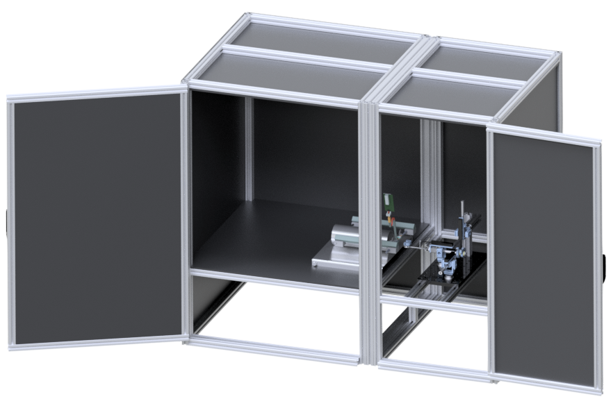
The enclosure houses the experiments and is made up of two compartments. The leftmost is a behavioral compartment which houses the animals. The rightmost is a hardware compartment which houses the robot and other peripheral devices (i.e., lights, solenoid, etc.). The CAD assembly for the enclosure is on our github .
The entire assembly is constructed from extruded aluminum (i.e., 80/20) and fastened using mostly anchor fasteners. This offers a high degree of modularity and adjustability. For example, the relative positioning of the animal and robot can be easily adjusted, and there are many options for connecting or removing peripheral hardware. 80/20 is pretty straightforward to work with; however, it is highly recommended to go over the company’s many tips and tutorials:
https://8020.net/product-basics
The behavioral compartment is relatively large at 26”x26”x52” (lwh). These dimensions were chosen with a range of in vivo neurophysiology experiments in mind. For example, the base dimensions are suitable for free-foraging hippocampal place cell or entorhinal grid cell experiments. The height was chosen so that a recording tether could reach all corners of the compartment without causing too much strain on the animal’s head.
Currently, the enclosure has two primary configurations: one for freely behaving animals, and a second for restrained animals. The configuration shown in the image above corresponds to the restrained condition. In that case, the body and/or head retraining device is merely placed inside the behavioral compartment, and the animal is given unimpeded access to the robot. In the free-moving condition, a plexiglass wall is inserted between the behavioral and hardware compartments. The animals is then allowed to freely explore the behavioral compartment and must reach through a slot in the plexiglass in order to interact with the robot.
Robot

The ReachMaster robot is a pneumatically-actuated, passively balanced, parallel robot with two rotational and one translational degrees of freedom (dof). The two rotational dof’s are controlled by two low-friction double-acting cylinders (Actuation) each connected to the base (Mounting) in parallel by a 2-dof gimbal (Gimbal). These two actuators are joined in series, by spherical joints, to a third cylinder which controls the translational dof. The translational actuator is also connected to the base by a 2-dof gimabal, and to the robot’s handle (Handles) and reward delivery unit (Reward Delivery). The reward delivery unit consists of a solenoid-driven liquid delivery spout, an IR beam-based lick detector (Lick Detection), and an option LED to provide visual cues. Lastly, fast high resolution position sensing is achieved by low-friction linear potentiometers (Position Sensing) attached to each of the cylinder rods. All data from the potentiometers, solenoid, LED, and IR sensors is recorded by a SpikeGadgets acquisition system (Data Acquisition).
The robot workspace (shown in red) can be empirically estimated by acquiring potentiometer data from the robot as it explores its full range of motion, passing the trajectory through an analytically-derived forward kinematics transformation (Kinematics), and then fitting a surface to the extrema of the resulting scatter plot (see link_to_code). Similary, command positions can be derived by sampling points from a relevant subspace of the robot workspace (e.g., the rodent workspace shown in blue), and then passing those points through an analytically-derived inverse kinematics transformation that returns the corresponding potentiometer values.
reachmaster.interfaces.robot_interface.load_config_commands()
Air Delivery
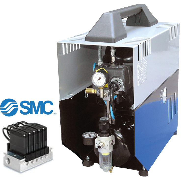
Our lab uses a custom-machined manifold to direct compressed air for pnuematics. We then route air through silenced S070 3-port solenoid valves. Calibration routines ensure that the measured pressure is matched to positional sensors, discussed below.
Actuation
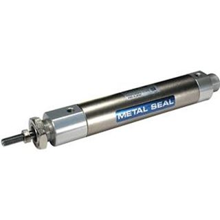
Our lab uses SMC cylindrical actuation to power robot movement.
Position Sensing
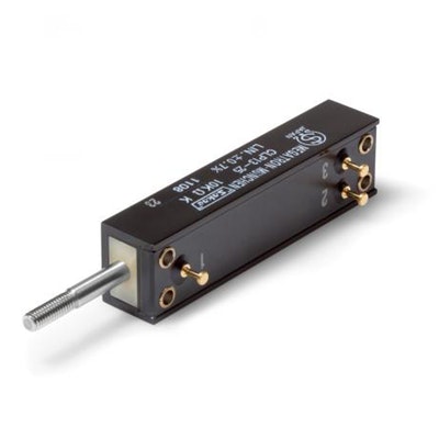
Our lab uses linear potentiometer sensing to ensure positions are highly accurate. Additional options include contactless sensing, which may provide more robust durability.
Handles
ReachMaster is able to accommodate unique handle types.
Auditory Cues
ReachMaster is able to provide auditory cues, delivered at the beginning of each trial. Auditory cues may be generated, then utilized in an experiment using the GUI.
Cameras
Our lab currently uses XIMEA-Q camera Lighting ——–
Lighting is provided by micro-controller operated NeoPixels LED light arrays (12x12). While setting intensity is not currently an option within the ReachMaster software, these parameters may be altered in experimental_microcontroller.cpp
Reward Delivery
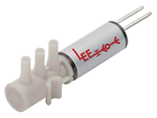
Water is delivered using a calibrated, micro-controller operated Lee solenoid.
Lick Detection
We use a modification of Feldman Lab’s lick detector. Documentation may be found at http://brianisett.com/2016/03/26/diy-lickometer/ Controllers ———–
Our lab uses Teensy arduino microcontrollers to operate robot and other sensors in the ReachMaster platform.
Data Acquisition
We gather sensor data from pneumatics and other electronics using the SpikeGadgets data acquisition hardware system. More information may be found at https://spikegadgets.com/ .
Compute Requirements
ReachMaster requires minimum installation on two local compute stations. One, controlling trodes and overhead camera data, requires 4+core CPU > 1.8 gb/s, 16GB memory minimum. The second requires 4+core > 2 gb/s, 32GB memory minimum. The second compute station will run the micro-processor and camera system as well as store data locally. It is advised to move raw data to cloud ASAP ( our lab uses a script after each experiment).
ECOG Headstage Casing
CAD design files for our ECOG grid casing, used for in-vivo neurophysiological recordings, may be found in the hardware design. 3-D print compatible files are included. Bouchard Lab currently uses a Form2 3-D printer with grey resin to print casing.